





Services · Optical Polishing
Optical Polishing Services
Surface figure, controlled roughness and application-specific optical finishing
Custom polishing requirements for optical glass components, reviewed from material and geometry through final inspection.
Review Polishing Specifications1. Custom Optical Polishing for Functional Glass Surfaces
Felix Glass supports optical polishing projects for custom windows, domes, lenses and display or instrument glass. The process is reviewed against the substrate, geometry, useful aperture and optical function.
Send a controlled drawing with the required figure, roughness and surface-quality criteria. A glossy appearance is not a complete optical specification; the finished surface must be evaluated against measurable requirements.
2. Optical Polishing Specification Overview
| Requirement | Information to provide |
|---|---|
| Substrate | Material grade, incoming condition and permitted alternatives |
| Geometry | Dimensions, curvature, thickness, datums and tolerances |
| Polished faces | Identify S1/S2, inner or outer surfaces and edge treatment |
| Clear aperture | Region over which optical limits apply |
| Surface figure | PV or RMS limit, reference shape, aperture and measurement basis |
| Surface roughness | Metric, units, scan area and spatial bandwidth |
| Surface quality | Defect grading method, grade and inspection conditions |
| Final configuration | Uncoated, coated, strengthened or assembled condition |
| Reports | Required measurements, sampling and traceability |
Achievable limits and inspection scope are confirmed for the specific design. This table is an RFQ checklist, not a universal capability guarantee.
3. Surface Figure, Roughness and Defects Are Different
Surface figure describes departure from the intended overall shape. Roughness describes finer surface texture within a defined measurement range. Scratches, pits and other localized defects require their own surface-quality criteria.
A surface may satisfy one requirement while failing another. State the properties that matter to the optical function separately, and avoid using “mirror finish” or “optical grade” as the only acceptance language.
4. Material Selection and Incoming Condition
The polishing route depends on material composition, hardness, geometry and the condition left by earlier processing. Optical glass, fused silica, borosilicate and sapphire projects require material-specific review.
Identify an exact grade where transmission, homogeneity or other bulk properties matter. Polishing cannot eliminate bulk absorption or convert an unsuitable substrate into the correct optical material. For customer-supplied blanks, agree on incoming inspection, stock allowance and responsibility for pre-existing defects before processing.
5. Flat Windows and Parallel Surfaces
For flat windows, specify each required surface figure together with thickness, wedge or parallelism. Define the clear aperture and any permitted edge exclusion. Mechanical thickness accuracy and optical flatness are separate requirements.
Where the transmitted wavefront is critical, specify it directly in the intended test configuration. A component’s transmitted performance depends on both surfaces and the material, so independent surface-flatness values do not automatically establish the complete optical result.
6. Curved Surfaces, Lenses and Domes
For curved parts, provide the nominal surface definition, radius or model, wall or center thickness and relevant alignment datums. State which surfaces must be polished and where optical performance will be evaluated.
Access to inner surfaces, curvature and wall stiffness affect processing and inspection. Dome and lens projects should identify the useful aperture and ray geometry. Requirements for centration, concentricity or transmitted performance must be stated when they are functionally important.
7. From Grinding to Polishing
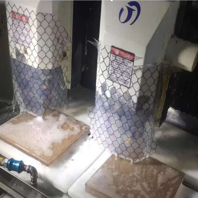
Earlier grinding establishes geometry and leaves a surface condition that must be considered in the finishing plan. Subsequent abrasive stages and polishing refine the surface while preserving the dimensional and optical targets.
The process requires adequate material allowance. Removing damage or correcting figure can change thickness or curvature. Specify the finished dimensions and permissible changes rather than treating polishing as a process that leaves all geometry untouched.
8. Write a Measurable Surface-Figure Requirement
State whether the limit describes surface departure, reflected wavefront or transmitted wavefront. If expressed in waves, include the measurement wavelength and the meaning of the reported value. Identify the test aperture and reference shape.
For curved surfaces, clarify whether power or radius error is controlled separately from residual irregularity. Agree on terms removed during data analysis, such as tilt or power, where they affect acceptance. Two reports using different apertures or processing rules may not be directly comparable.
9. Specify Roughness with Its Measurement Conditions
Give the required roughness metric and units, and define the sampling area or length and relevant spatial bandwidth. A nanometer value without those conditions can leave ambiguity about the surface texture being assessed.
Roughness is relevant to scatter, but a local measurement does not describe all spatial scales or every part of a surface. Agree on measurement locations and representative coverage. Use a method suitable for the surface and the specified range rather than assuming one instrument answers every optical question.
10. Define Surface Quality and Edge Acceptance
Specify the grading system for scratches and digs or other surface imperfections, including inspection lighting and the applicable aperture. Do not assume different grading systems are directly interchangeable.
Define edge chips, bevels, polished edges and contact regions separately. A defect outside the optical aperture may still matter for sealing, mounting or handling. Inspect according to the agreed functional and cosmetic requirements rather than appearance alone.
11. Prepare for Coating, Strengthening and Assembly
Identify later AR or other coatings, cleaning, strengthening, printing and bonding steps during the polishing review. Surface preparation and cleanliness need to support the next operation.
State whether acceptance applies before or after these steps. Coating stress, thermal processing or mounting can change figure or appearance. Strengthening is not required for every optical part and must be compatible with the substrate and optical function.
For laser applications, provide wavelength and operating conditions plus any required damage qualification. Low roughness alone is not a laser-damage-threshold guarantee.
12. Inspection and Report Scope
Inspection can include dimensions, surface figure, roughness and surface quality as required by the drawing. Agree on sampling, test conditions and report format before production, including how measurement uncertainty is treated near limits.
Reports should identify the part and drawing revision, measured aperture or area, instrument or method, processing assumptions and actual results. Confirm any specialized testing scope during quotation; a service description should not be read as a claim that every test is performed on every part.
13. RFQ, Prototypes and Protective Packaging
Send the drawing, material, polished-face identification, aperture, optical limits, final coating condition and quantities. Include the application, mounting constraints and required delivery destination so functional priorities are clear.
Paid prototypes can be quoted for evaluation before production release. Tooling, minimum order quantity, lead time and pricing depend on the reviewed scope. For repolishing, include the current condition and acceptable material removal; restoration is not guaranteed without inspection.
Packaging should prevent movement and contact with polished surfaces. Define supports, separation, cleanliness and labels for vulnerable shapes. Keep the approved drawing and inspection basis with repeat orders.
14. Frequently Asked Questions
Does a mirror-like surface prove optical quality?
No. Surface figure, roughness and localized defects require separate limits and measurements.
Can polishing improve a ground optical surface?
It can be part of the finishing route, provided the material, damage condition and remaining allowance support the required result.
Does polishing change thickness or curvature?
It removes material and can change geometry. Finished dimensions and permitted correction must be included in the specification.
Can inner and outer dome surfaces be polished?
Submit the geometry for review. Access, curvature, wall thickness and inspection requirements determine feasibility.
Are scratch-dig grade and roughness the same?
No. They describe different surface characteristics and need separate acceptance criteria.
Can an existing scratched optic be repolished?
Possibly after assessment. Material removal, remaining thickness, curvature, coatings and damage depth can limit restoration.
Should optical requirements apply before or after coating?
State the condition explicitly. If final coated performance matters, define finished-component acceptance.
What information is needed for a polishing quote?
Provide material, drawing, polished faces, clear aperture, figure, roughness, defect criteria, quantities and required reports.
15. Request an Optical Polishing Review
Discuss your component’s optical function and drawing requirements with Felix Glass. Identifying the critical surfaces and measurable acceptance criteria helps establish a practical finishing and inspection plan.
Dongguan Felix Glass Co., Ltd.
Email: james@felixglass.com
Phone: +86-18565032888