

Products · Custom ITO Conductive Glass
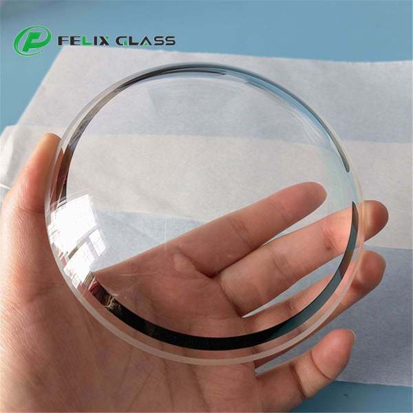
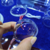
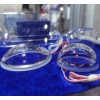
Custom ITO Conductive Glass Dome
Custom curved conductive optics for heating, sensing and optical integration
19+ years optical glass manufacturing · dome geometry & per-lot resistance inspection
Custom ITO-coated glass domes with drawing-based geometry, optical transmission, sheet resistance and electrode requirements. Prototype and production inquiries welcome.
1. Transparent Conductivity on a Custom Glass Dome
Felix Glass supports custom glass dome projects incorporating an indium tin oxide (ITO) conductive layer. The dome provides the optical and mechanical interface; the coating adds an electrically conductive surface for a defined function such as resistive heating or charge dissipation.
Each project is reviewed around the drawing, operating spectrum, electrical targets and installation conditions. Curvature, coating accessibility and electrode placement are evaluated together before the specification is confirmed.
2. Custom Specification Overview
| Parameter | Specification basis |
|---|---|
| Geometry | Hemisphere, spherical cap or flanged dome to approved drawing |
| Dimensions | Outer and inner geometry, height, wall thickness and flange features |
| Substrate | Optical glass, borosilicate or fused silica grade subject to application review |
| Coated face | Inner or outer face, subject to process access and design review |
| Sheet resistance | Target and tolerance in Ω/□; mapped over agreed locations |
| Optical performance | Finished-part transmission over the specified band and viewing angles |
| Electrodes | Contact locations, busbar layout and connection scope to specification |
| Optical quality | Clear aperture, surface quality and wavefront or imaging requirements |
| Environmental performance | Exposure conditions and post-test electrical and optical limits |
| Quantity | Prototype and production quantities quoted separately |
Numerical targets are confirmed for the selected material, geometry and coating stack. Flat-glass catalog values should not be treated as guaranteed specifications for a custom dome.
3. Glass Materials and Spectral Compatibility
Candidate substrates include suitable optical crown glass, borosilicate glass and fused silica. Selection depends on the wavelength band, optical quality, thermal exposure and forming or polishing requirements. Specify a manufacturer grade where material identity is mandatory.
Both substrate and ITO stack must transmit the operating wavelengths adequately. Visible transparency does not establish transmission at 905, 940 or 1550 nm, or in a thermal-imaging band. Provide the full source and detector bands for review.
4. Dome Geometry and Clear Aperture
Provide inner and outer surface definitions, opening diameter, overall height, flange dimensions and wall-thickness requirements. Define reference axes and mounting interfaces, and state whether optical aperture dimensions are projected or follow the curved surface.
Identify the viewing region separately from busbars, masked edges, sealing lands and adhesive zones. Specify image quality across the required field rather than only at the dome center. Coating and electrode placement must preserve the usable optical path.
5. ITO on Curved Surfaces
Conductive films can be deposited on suitable curved substrates, but thickness distribution and electrical uniformity depend on geometry and process access. Inner-surface access, steep curvature and edge regions require project-specific review.
Depositing ITO on an already formed dome is different from bending coated flat glass. Do not assume a film qualified on a flat sample will survive a later forming step or retain the same resistance after deformation. The proposed manufacturing sequence must be qualified for the actual part.
6. Sheet Resistance and Electrical Uniformity
Specify sheet resistance in ohms per square (Ω/□), including tolerance, measurement temperature and sampling positions. Sheet resistance describes the conductive film; it is not the same as the resistance measured between the installed terminals. For background, see our sheet resistance explained guide.
Terminal resistance also depends on current-path geometry, contact layout and contact resistance. The familiar rectangular-film relationship R = RₛL/W applies under its ideal planar geometry and electrode assumptions. It should not be applied to a dome by substituting its diameter for both dimensions.
Agree on a curved-surface measurement method and electrode-to-electrode checks. A flat witness coupon can support coating-process monitoring but does not by itself prove resistance uniformity over the dome.
7. Transmission, Reflection and Coating Appearance
Specify minimum or average transmission, wavelength interval, incidence conditions and the clear aperture. Identify whether performance is required through the complete dome or for an individual coated interface.
Conductivity and transmission must be balanced in the selected stack. ITO thickness, optical matching layers and substrate properties affect spectral response and reflected color. Request data for the relevant band rather than judging performance by visible appearance alone. Trade-offs are covered in the transmission vs conductivity guide.
Where imaging is critical, include haze or scatter, wavefront or image-quality limits, and acceptable changes across the field of view.
8. Transparent Heating and Condensation Control
An ITO layer can act as a resistive heater when connected to a suitable electrical supply. A heating design can support condensation control when it maintains the relevant surface above the dew point under the specified environment. Heating physics and power control are detailed in the ITO heating principles guide.
Provide supply voltage, power limit, ambient range, humidity, airflow, warm-up target and maximum permissible surface temperature. Heating uniformity depends on electrode layout, heat loss through the mount and temperature-dependent electrical behavior.
De-icing is a separate load case requiring ice conditions and removal-time targets. A conductive dome alone is not a complete regulated heating assembly; controller, sensing, wiring and protection responsibilities must be defined.
9. Busbars, Contacts and Electrical Interfaces
Identify contact pads, busbars and lead attachment locations on the drawing. Specify contact resistance, mechanical attachment and environmental exposure requirements where applicable.
Electrode layout should control current distribution while avoiding obstruction of the optical aperture. A continuous conductive ring is not automatically an effective heater arrangement without a defined second electrode and current path.
Confirm whether the order covers only the coated dome, deposited contacts, attached leads or an assembled heater. Lead strain relief, insulation and sealing must be addressed at the agreed assembly level.
10. Additional Optical and Protective Treatments
AR or optical matching layers may be considered where compatible with the ITO electrical function. Protective layers can be reviewed for exposed surfaces, with contact regions left accessible as required.
Any additional layer can affect transmission, reflection, adhesion, resistance access or cleaning behavior. The complete stack must be evaluated on the chosen substrate. Do not assume that separately qualified coatings retain their specifications when combined.
Assign inner and outer faces explicitly. The best location for environmental protection may differ from the best location for electrical access or process uniformity.
11. Application Options
| Application | Potential role | Important review point |
|---|---|---|
| Camera and sensor enclosures | Heated transparent protective dome | Image quality, field of view and condensation conditions |
| Optical instruments | Conductive curved optical interface | Transmission, electrical continuity and dimensional stability |
| Environmental monitoring | Condensation-control surface | Weather, cleaning and power budget |
| Charge-dissipative structures | Controlled discharge path | Grounding, resistance and connection reliability |
| EMI-related optical interfaces | Conductive element within a shielding design | Frequency range, grounding, seams and assembly-level attenuation testing |
Sheet resistance alone does not establish electromagnetic shielding effectiveness. Any attenuation target must be verified for the installed enclosure and its interfaces.
12. Inspection and Qualification
Agree on optical, dimensional and electrical inspection before production. Typical review items include geometry, wall thickness, optical aperture, surface condition, spectral transmission, resistance mapping and terminal resistance where contacts are supplied.
For heated assemblies, specify the test fixture, power conditions, ambient environment and temperature-map acceptance limits. Include post-exposure optical and electrical measurements for relevant humidity, temperature-cycle or cleaning tests.
Reports should identify drawing revision, sample or lot, measurement conditions and whether data are from the finished dome or a witness coupon. Certification and specialized qualification requirements must be confirmed in the quotation.
13. Prototype, Packaging and Production Planning
Prototype evaluation is useful for checking resistance distribution, optical appearance, contact layout and mounted thermal behavior before fixing production requirements. Request separate prices for the development quantity and expected production batches.
Specify packaging that protects the coated face and prevents loads on electrical contacts. Include part labels, orientation identification and handling instructions as needed. Manufacturing schedule, delivery terms and report scope are confirmed for each order.
Before release, approve the substrate, coating stack, electrode layout and acceptance criteria, and establish how subsequent design or process changes will be reviewed.
14. Frequently Asked Questions
Can ITO be applied to a curved glass dome?
Suitable curved substrates can be coated. The specific dome geometry, coated face and required uniformity need process review.
Is the sheet resistance the same as terminal resistance?
No. Terminal resistance also depends on geometry, electrode placement and contact resistance.
Can the dome prevent condensation without electrical power?
ITO does not provide active heating without power. Other passive effects must not be assumed from the conductive coating alone.
Will visible transparency guarantee LiDAR wavelength transmission?
No. Require spectral data at the actual operating wavelengths and angles.
Can the inner surface be coated?
It can be evaluated, but access, curvature, fixturing and coating uniformity determine feasibility.
Can AR and ITO be combined?
A compatible stack can be evaluated, with optical performance, contacts and durability qualified together.
Are power supplies and controllers included?
Only when explicitly included in the quotation. Define the scope of the coated part, electrical connections and complete assembly.
What should I send for an RFQ?
Send a drawing, substrate preference, wavelength band, sheet-resistance target, electrode layout, heating or grounding requirements, environment and quantities.
15. Request a Custom ITO Glass Dome Quote
Send your dome drawing and operating requirements to Felix Glass. Include prototype and production quantities, coated-face designation, clear aperture, transmission targets, electrical requirements and the requested delivery destination.
Dongguan Felix Glass Co., Ltd.
Email: james@felixglass.com · Phone: +86-18565032888