


Products · Custom ITO Conductive Glass
Custom ITO Heater Glass
Transparent resistive heating for anti-fog windows, cameras and optical instruments
19+ years optical glass manufacturing · ISO 9001 · mounted thermal & sheet-resistance inspection per lot
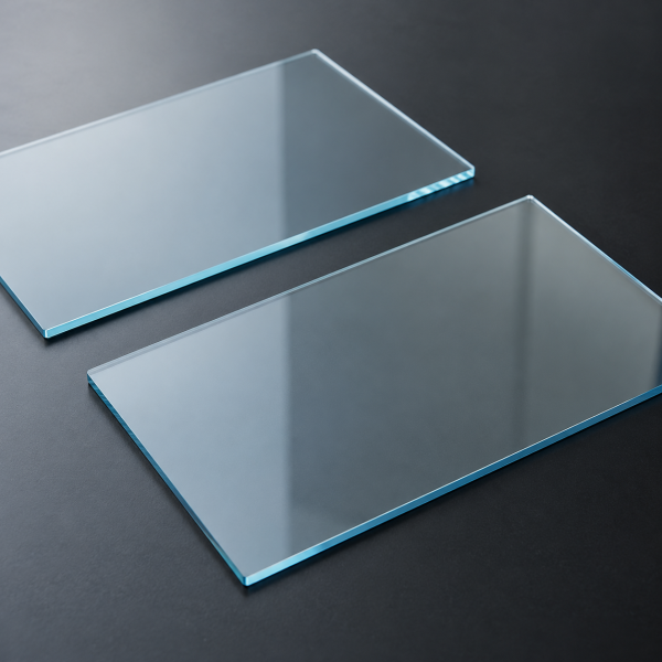
Custom ITO heater glass with application-specific resistance, contacts and optical performance for condensation control, de-icing and instrument integration. Manufactured by Dongguan Felix Glass Co., Ltd., a China custom optical component manufacturer.
1. Transparent Heating for Optical Windows and Displays
Felix Glass supports custom ITO heater glass projects combining optical transmission with resistive heating. An indium tin oxide film carries current between designed contacts, generating heat across a defined area.
Specify the window geometry, optical band, available power and operating environment together. A successful heater design balances temperature performance, transmission, contacts and mounting rather than selecting a sheet-resistance value in isolation. The underlying heating physics are covered in our ITO glass heating principles and power control guide.
2. Custom Specification Overview
| Parameter | Specification basis |
|---|---|
| Glass format | Rectangular, circular or custom outline; curved requirements reviewed separately |
| Substrate | Suitable soda-lime, borosilicate, optical glass or fused silica grade |
| Dimensions | Outline, thickness, holes, edge finish and clear aperture to drawing |
| ITO film | Sheet resistance, tolerance, coverage and optical requirements |
| Power supply | Voltage range, current limit, available power and control method |
| Heater resistance | Terminal resistance at a stated reference temperature |
| Electrodes | Busbars, pads, contacts and lead attachment scope |
| Thermal targets | Warm-up time, temperature range and uniformity under defined conditions |
| Optical targets | Transmission band, reflection, haze and imaging requirements |
| Qualification | Mounted thermal tests and relevant environmental exposure |
All numerical performance targets require confirmation for the specific geometry and assembly. A supply voltage alone does not define heater output or temperature.
3. Select the Substrate and Mechanical Geometry
Choose glass grade based on the optical band, thermal gradients, mounting and environmental exposure. Include thickness, edge quality, holes and any strengthening requirement in the drawing.
Identify the heated region separately from the clear optical aperture, sealing lands and contact areas. For shaped parts, provide a controlled drawing and model. The substrate, conductive film and contact structure must remain compatible with later bonding or assembly processes.
4. Specify Transmission with the Electrical Target
ITO conductivity and optical response depend on the film and layer stack. Provide minimum or average transmission across the actual source and detector bands, with angle and polarization requirements where relevant.
Do not infer near-infrared transmission from visible clarity. For camera windows, also specify image-quality or scatter limits; for displays, evaluate the cover with the intended display, illumination and viewing angles. Optical matching or AR layers can be reviewed as part of the complete stack. Film-stack and substrate trade-offs are explained further in the ITO glass transmission vs conductivity guide.
5. Understand Sheet Resistance and Terminal Resistance
Sheet resistance Rₛ is expressed in Ω/□. For an ideal uniform rectangular film with full-width contacts on opposite edges, terminal resistance is R = RₛL/W, where L is electrode spacing and W is the width perpendicular to current flow.
The relationship excludes contact resistance and assumes a simple current path. Circular parts, narrow contacts, holes, branches and patterned zones require suitable modeling or measurement. Specify terminal resistance and its reference temperature in addition to film sheet resistance when electrical power is critical. For background, see sheet resistance explained.
6. Connect Voltage, Resistance and Power
For a resistive DC load at the stated operating condition, I = V/R and P = V²/R. These equations describe electrical input; they do not predict surface temperature without the thermal boundary conditions.
At fixed voltage, lower resistance increases power and current demand. It does not automatically improve the design. Confirm the operating resistance, supply limits, contacts and thermal requirements together.
Not sure what supply and resistance combination your window needs? Send the drawing, available voltage and target temperature — our engineers will check the numbers against the real thermal boundary conditions, not just the ideal formula.
Send Parameters for Engineering Check7. Define Temperature and Warm-Up Requirements
Provide ambient temperature, airflow, humidity, mounting material, orientation and any liquid contact. State the target surface temperature, warm-up time and maximum permitted temperature at all critical locations.
Heat losses through the frame and exposed surfaces determine the temperature reached for a given input. A heater tested freely in still air may behave differently in a sealed housing or an aluminum mount. Define the fixture and operating state used for acceptance.
8. Control Heating Uniformity
Uniformity depends on film resistance distribution, electrode geometry and thermal losses. Narrow tracks, local damage, poor contacts and changes in current-path width can create unwanted local heating.
Specify the evaluation area, temperature-map method, stabilization time and allowable variation. Separate the usable optical region from contact zones when different temperature limits apply. Multi-zone or patterned designs can be reviewed where a continuous film cannot meet the requirement.
9. Busbars, Leads and Connection Scope
Define busbar location, width, pad layout and lead exit direction. Keep opaque contacts outside the required optical aperture where possible, and specify their mechanical and environmental requirements.
Agree on contact resistance, attachment process, strain relief and insulation. Do not assume that bare ITO can accept every soldering or bonding process. Confirm whether supply includes the coated glass only, contacts, leads or a more complete assembly.
10. Temperature Control and Integration
ITO heater glass requires an appropriate power and control arrangement for the application. Specify temperature-sensor location, regulation method, operating limits and the required response to abnormal conditions.
The conductive coating is not an insulating barrier or an inherently self-regulating thermostat. Define insulation from accessible surfaces and mounting hardware, connection protection and system-level verification as part of the assembly design. Controllers, sensors and power supplies are included only when agreed in the quotation.
11. Anti-Fog and De-Icing Applications
For condensation control, the design should maintain the relevant surface above the local dew point under the specified conditions. Define whether the goal is preventing condensation or clearing existing moisture, since these can require different power and time targets.
De-icing additionally requires ice thickness, starting temperature, wind or airflow, exposure and clearance-time targets. A successful anti-fog test does not establish de-icing performance. Confirm both optical clarity and temperature limits during representative testing.
12. Typical Applications and Coating Options
| Application | Design focus |
|---|---|
| Camera and sensor windows | Condensation control with retained image quality |
| Outdoor displays | Readability, cold-start behavior and weather exposure |
| Optical instruments | Transmission and controlled thermal conditions |
| Inspection viewports | Clear viewing region, cleaning and mounted thermal behavior |
| Laboratory equipment | Defined heating area, stability and integration with the test setup |
AR, protective or other functional layers can be reviewed where compatible with the electrical design. Additional coatings, laminates and adhesives can change optical performance and heat flow, so qualify the finished configuration.
13. Inspection, Prototypes and RFQ Checklist
Inspection can include dimensions, sheet-resistance mapping, terminal resistance, contact integrity and spectral transmission. Thermal qualification should identify supply conditions, fixture, ambient environment, temperature measurement method and acceptance limits.
Evaluate representative prototypes before fixing production requirements. Include post-exposure checks for relevant temperature cycling, moisture and cleaning. Define reports, sampling, packaging that protects contacts, and the scope of any attached wiring.
A structured list of every field above — with the order they should be answered in — is in our custom optics RFQ checklist.
Submit Your ITO Heater RFQ14. Frequently Asked Questions
Can you make a 12 V or 24 V ITO heater?
These supply requirements can be reviewed. Geometry, resistance, power and thermal conditions must be specified together.
Does 5 Ω/□ mean the complete heater is 5 Ω?
Only for an ideal one-square current path with the required electrode assumptions and negligible contact effects. Other geometries have different terminal resistance.
Can I calculate temperature from voltage alone?
No. Resistance, input power, heat losses, mounting and the operating environment are also needed.
Is lower sheet resistance always better?
No. At a fixed voltage it increases current and power, which may exceed the intended electrical or thermal limits.
Does the glass automatically regulate its temperature?
No self-regulating behavior is assumed. Specify appropriate sensing and control for the application.
Can AR coatings be combined with the heater?
A compatible stack can be reviewed, with optical, electrical and thermal performance evaluated together.
Are leads and controllers included?
Only when listed in the agreed supply scope. Identify contacts, leads, sensors and control hardware separately.
Will an anti-fog heater also remove ice?
Not automatically. De-icing needs a separate environmental load case and a defined removal-time test.
15. Request a Custom ITO Heater Glass Quote
Send your drawing, optical requirements and thermal operating conditions to Felix Glass. Include the available power supply, contact layout, prototype and production quantities, and delivery destination for a project-specific review.
Dongguan Felix Glass Co., Ltd.
Email: james@felixglass.com
Phone: +86-18565032888